IC9700 Interface to run Bodnar injection unit on 2 x IC9700s
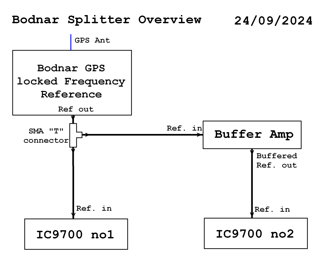
Run 2 x IC-9700s off one Bodnar GPS Unit
Firstly I checked what signal was available by tapping into the GPS reference output coax with a “T” joiner.. The CRO measured about 7v P-P
I built a simple buffer circuit so not to load up the existing signal to the original unit. The circuit uses a single garden variety transistor, BC547, which has plenty of gain and a FT of ~200mhz. It is in emitter-follower configuration so has high input impedance so as not to load up existing circuitry to 1st radio, unity gain, and very low output impedance to drive my bodged-up home made injector unit for the 2nd radio..
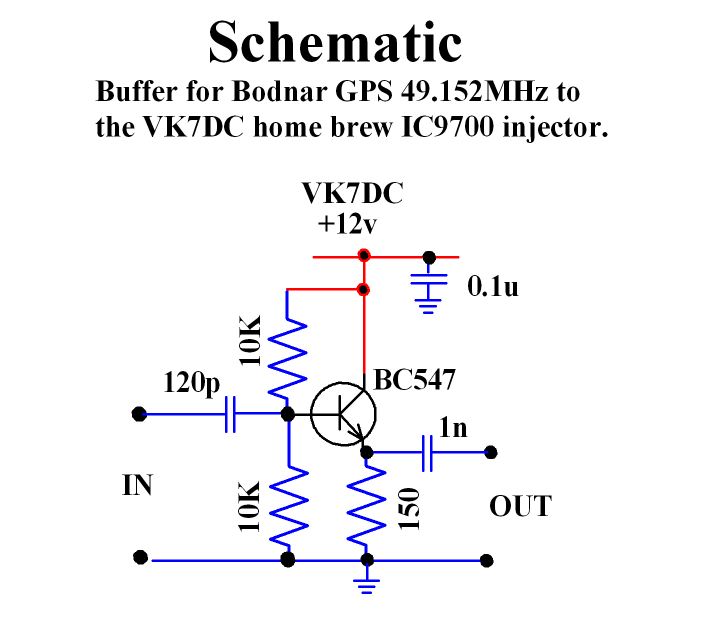
So testing the buffer circuit unit I ended up with almost 7v P-P.output. The buffer circuit is mounted externally to the radio in a plastic box and powered by a small fly lead connected to the radios main power cable.
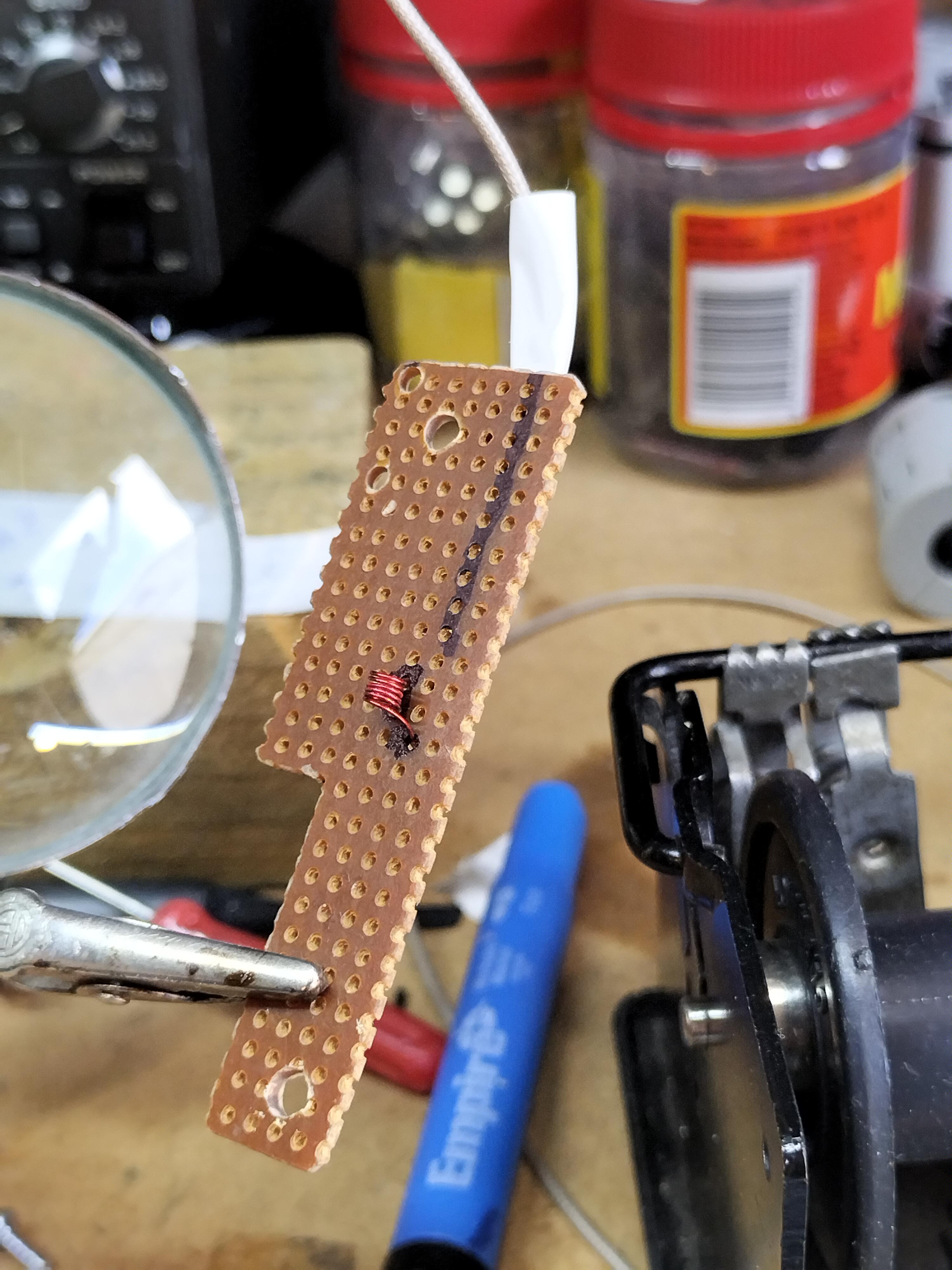
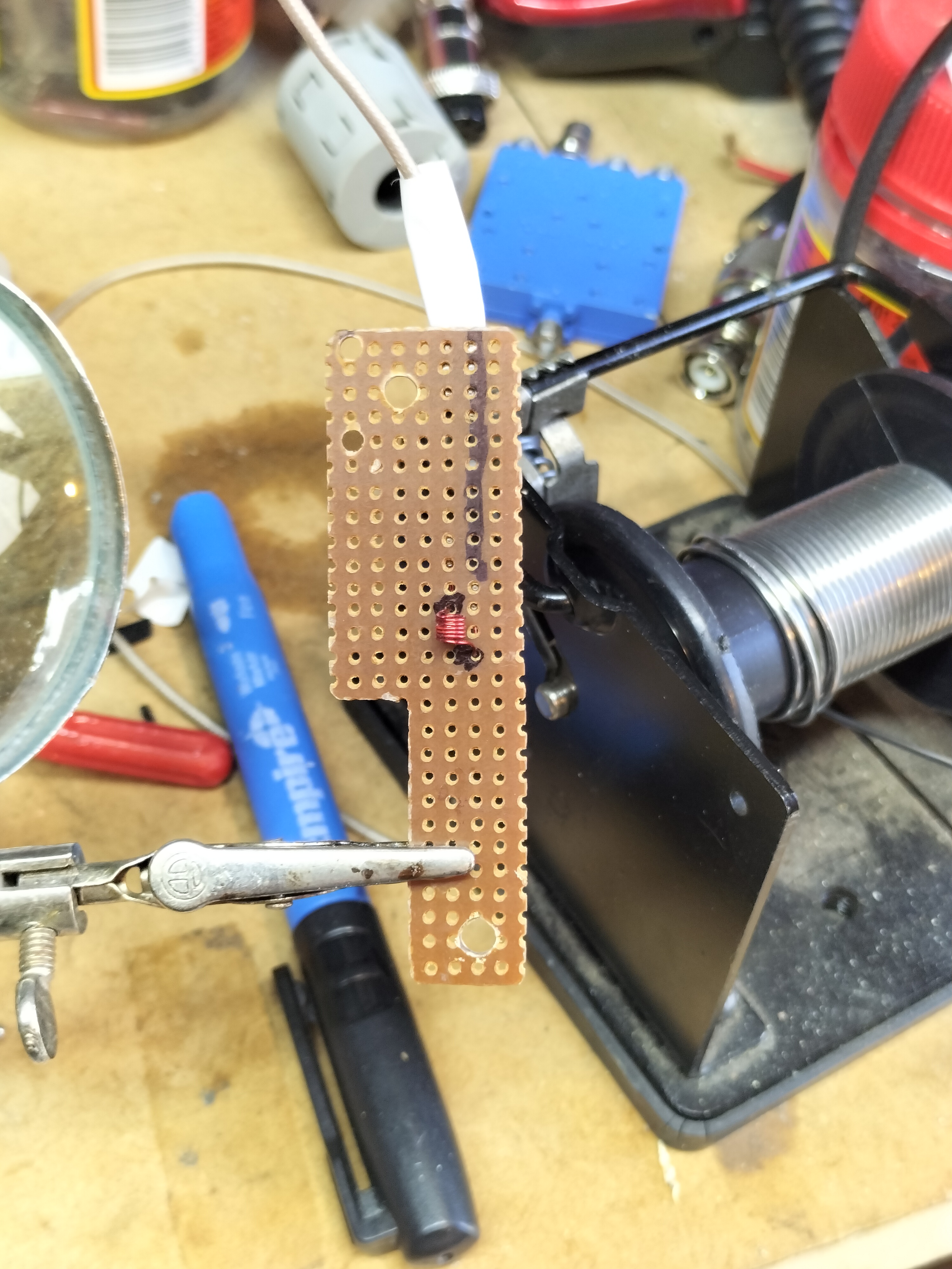
The injector consists of a small coil and 100pf capacitor in series mounted on a bit of vero-board and could be used in place of purchasing a Bodnar injector PCB if trying to save money and only one IC9700 is to be used. Only the Bodnar GPS unit would be required.
The Bodnar GPS unit itself produces about 7v P-P when adjusted to max output.
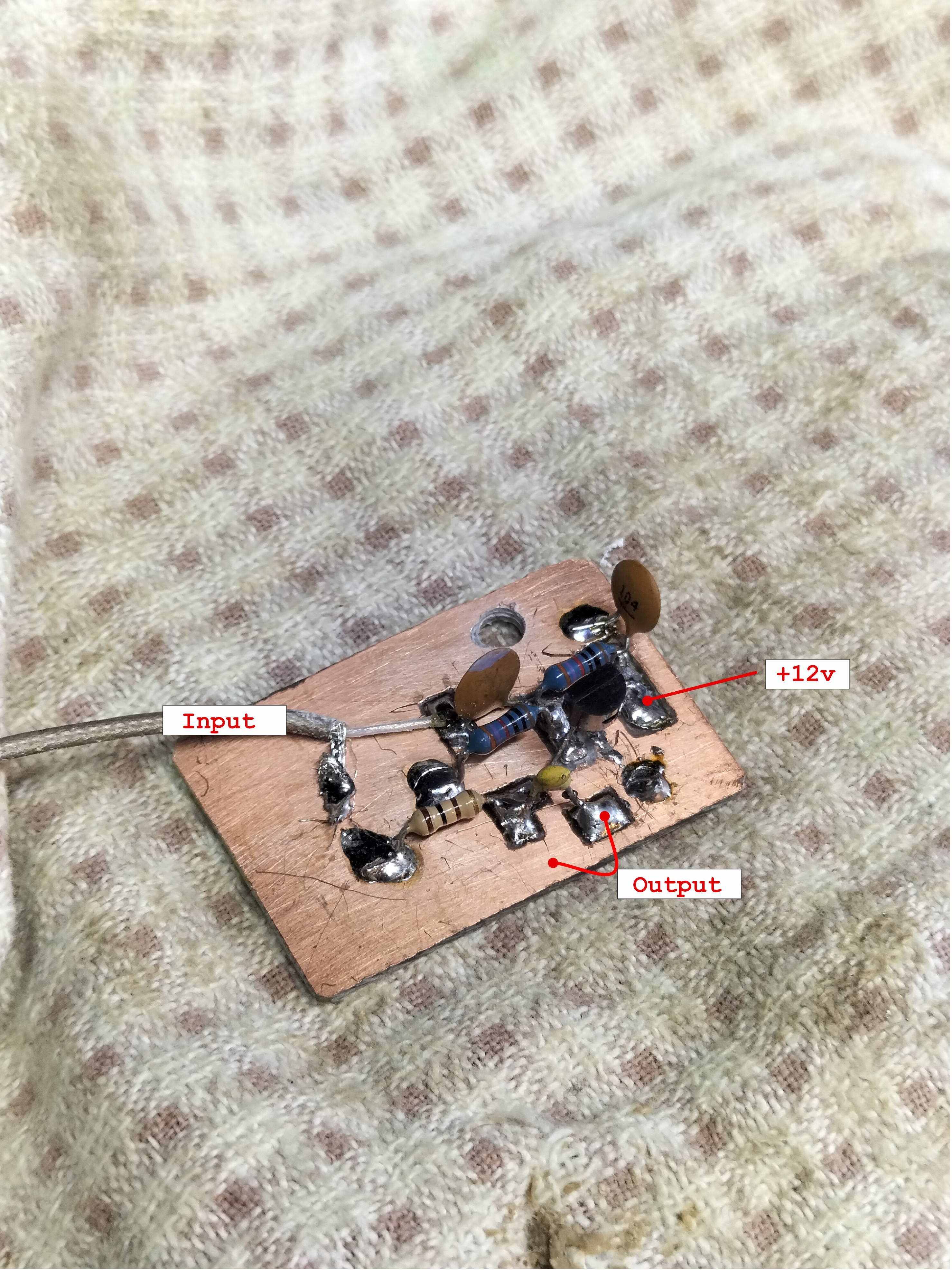
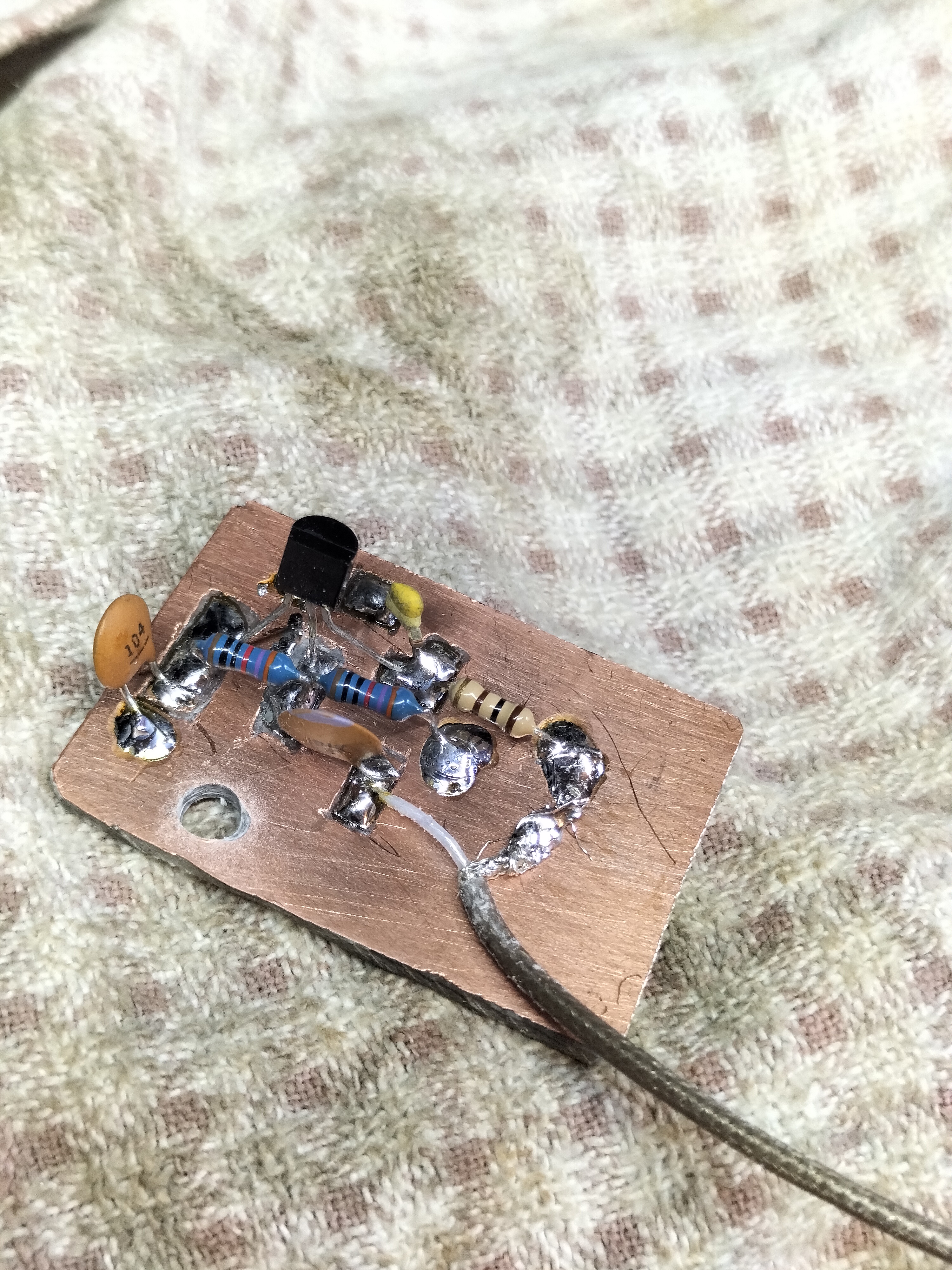
Buffer built on blank single sided PCB. Isolated pads cut with a small
diamond tipped rotary engraving tool.
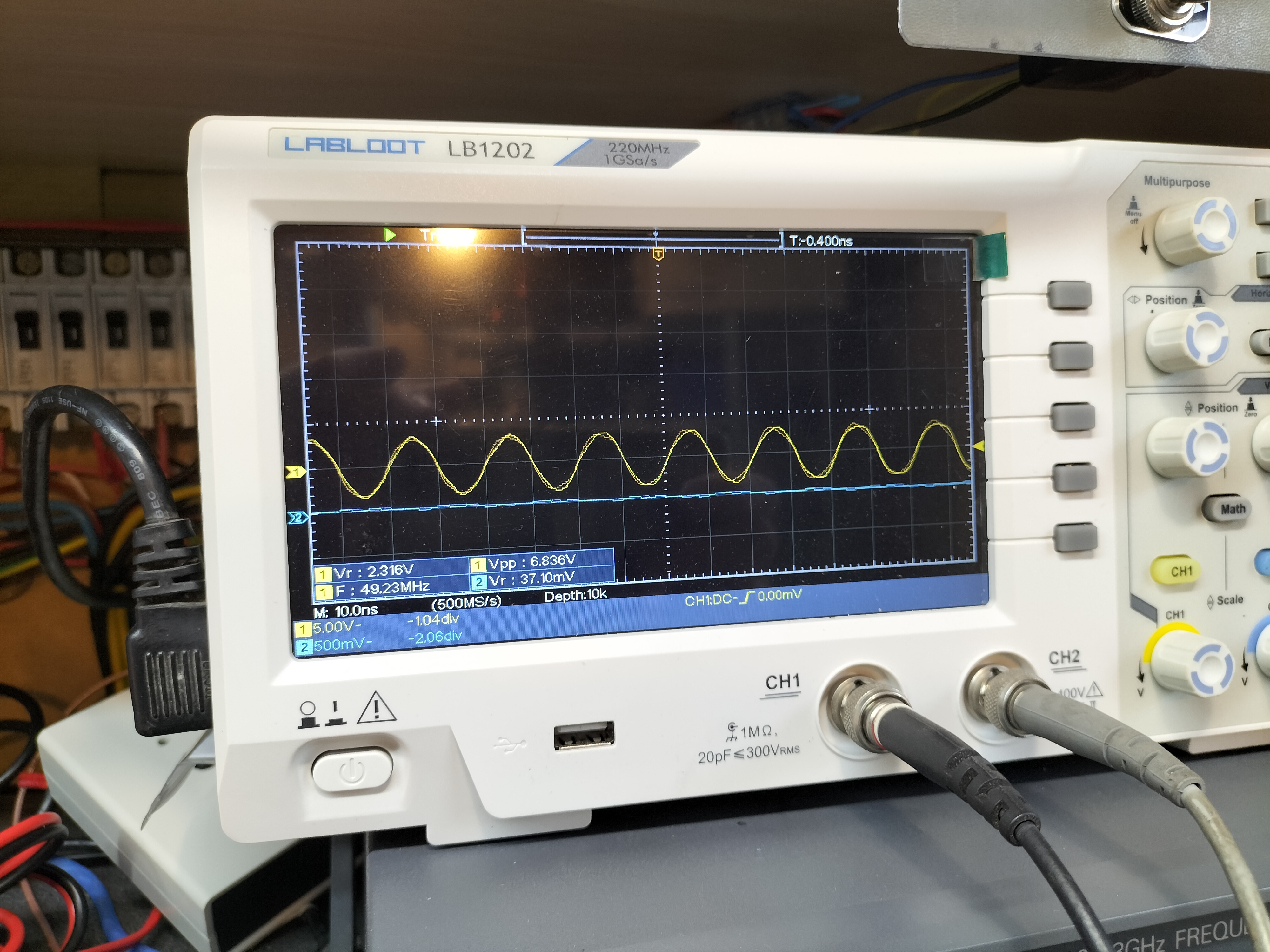
As the oscilloscope shows, circuit output is 6.8v P-P
The HOME BUILT INJECTOR..
COIL VIEW
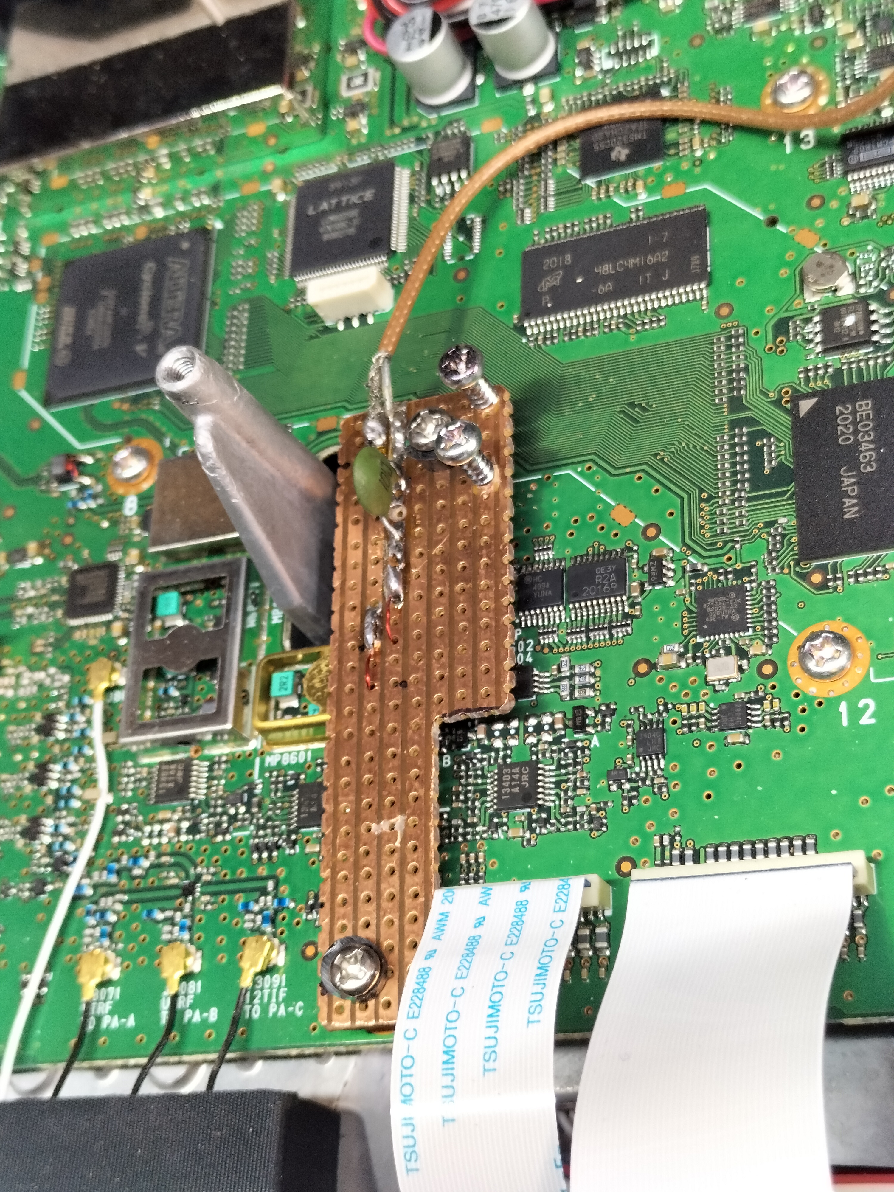
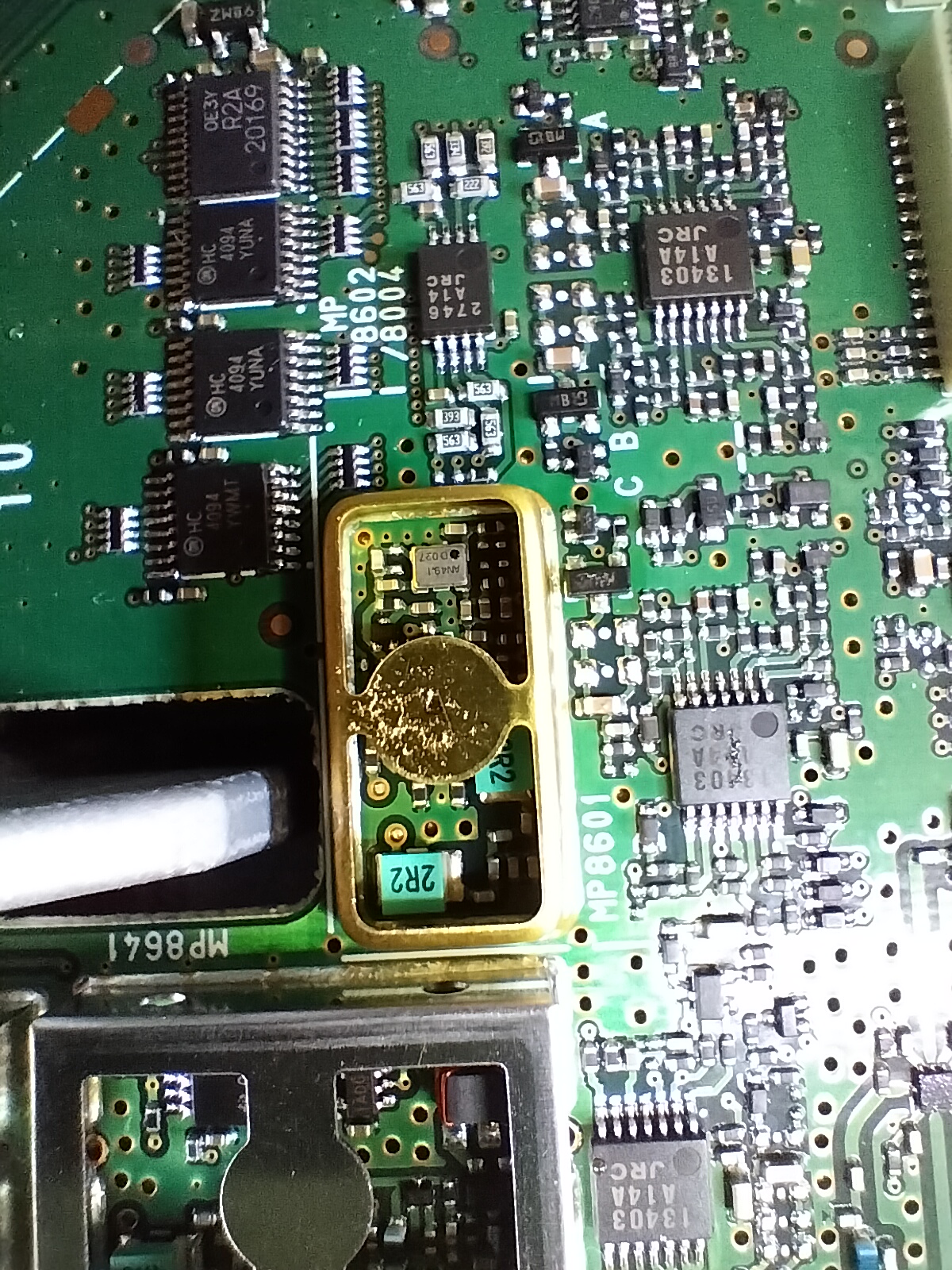
Top view of coil and coax connections View of TCXO inside top half of shield
The coil 5 turns and is tight wound on a 3/32” drill shank. Wire size is 0.35mm enamelled wire and once the board is mounted the coil sits inside the brass shield around the radio’s reference VCXO.
NOTE: A 100pf capacitor is in series with the coil and is mounted and soldered on top of board across a small gap cut in the track.
As per Bodnar instructions the radio’s reference setting needs to be set so the GPS signal has to exert only a minimal pull on the TXCO.
At 23cm, the calibration should be within 50hz before applying the GPS signal, although in testing I was able to get a lock within 900hz, but that leaves little room for thermal drift.
Best way is to check is listen to a GPS locked beacon on upper SSB with dial at 1khz low offset, i.e. if beacon is 1296.434Mhz then set dial to 1296.433Mhz and check audio with WSJT-X program monitoring the waterfall.
Allow the radio 10 minutes to warm up from cold. Get to within 50hz using the menu Settings-Function-Ref adjustment. Adjust the coarse adjustment + or – to get close.
Apply the GPS reference and audio tone should change to the correct 1khz mark smoothly without jittering once applied.
Enclose buffer amp in a box and fit connectors as required. I used SMA fittings and flyleads
sourced from AliExpress at a reasonable price.
Time for a beer.
VK7DC 20230415 rev2