
After moving house and a 10 year absence from 6M, 2M & 70CM SSB, I
finally restored my old 2M and 70CM antennas, but the 6M beam was a
bit too cumbersome having a 5m long 50mm diameter aluminium boom.
Wind loading is a big factor in NW Tasmania, so a rethink was
required.
Using
readily available material from the local hardware shop a 3 element
beam was constructed.
The
design is NBS (National Bureau of Standards) which were developed
around the late 70’s for various sized optimised yagis with
computation charts for various diameter and elements Vs various
length booms.
This
design consists of 3 elements with nominal 7.2dBd gain with elements
of 12mm dia. reducing to 10mm dia. ends and a 25mm square aluminium
boom.
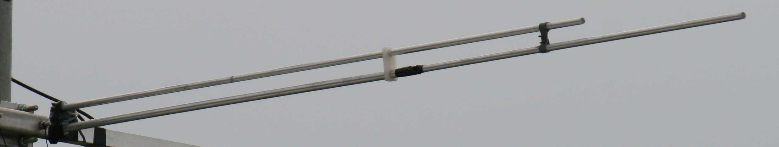
The
match device is a cross between Gamma match and a half folded dipole,
chosen because if its simplicity and DC grounding of the coax. A
gamma match uses a capacitor to cancel out the inductance of the
gamma rod, whereas in this system the capacitor is gone and driven
element length and
matching point is altered to give the impedance
match and cancellation of reactance.
Requirements:
Pedestal
drill
Battery
drill
1/8”,
13/32, 10mm & 12mm drill bits
1/8th
Aluminium rivets and rivet gun
Self
tapping screws 12mm long
1 x
3m length 25x25x1mm square aluminium,
2 x
3m length x 10mm dia round aluminium tube
2 x
3m length x 12mm dia round aluminium tube
100mm
of aluminium strip 12mm wide x 1mm thick to make the gamma
rod/element connecting strap.
Some
25mm wide x 5mm thick x 50mm long strips of plastic to make supports
for gamma rod. You might find a plastic chopping board in the kitchen
to cut a bit off while the boss is not looking. This material is not
real critical as to what you use as long as it is stable in the heat
and weather.
Construction:
Boom
(25mm Square) – Using a bench/pedestal drill and a 12mm twist bit
make 3 holes centrally at the relevant positions for each of the
elements and
cut off the excess length.
Elements - Cut one 3m length of 12mm tube into 2 sections,
so you end up with
1420mm and 1580mm. One cut required.
The
short length will be for the director and the long one will be for
the reflector.
The
second 12mm tube is cut in half giving 2 pieces 1.5m long. One piece
is for the driven element, the other piece is now spare.
The
inside diameter of the 12mm tube that I purchased was slightly
smaller than 10mm and the 10mm tube was about 0.1mm oversize, so each
end of all the 12mm dia sections needed drilling out.
I
used a 13/32" drill bit in a battery drill, The 12mm sections will need
holding firmly in a vice and a generous amount of spray lubricant
(e.g. CRC, WD40 etc..) used on the drill bit to prevent aluminium
adhering to the drill bit and causing seizing.
Drill
depth will be 80-90mm. Clean swarf out regularly and add more spray.
Cut
the 10mm dia tube to 6 x 750mm sections for the ends of all the
elements.
Mount
the element centre sections centrally in their correct locations in
the boom using the self tapping screws to hold them secure. Do not
drill/screw into the elements as this weakens them, just let the
screws push tight against them. Put a bead of Silastic around the
tubes where they fit through the boom. This is to prevent wind
vibration eventually wearing through the elements.
At
this point the 10mm dia sections should be fitted in the reflector and
director to get the overall length required and then pop riveted into
place. I used 2 pop rivets about 50mm apart for each join.
Do
not rivet driven element tips in place until matching is completed.
Matching rod:
The
2 insulating supports consist of a 12mm and 10mm hole 30mm apart in a
50mm long 6mm thick piece of plastic and need to be installed on one
side of the 12 mm driven element section.
The
matching rod (1100mm long 10mm dia) has a 10mm long section at the
end where 1/2 of the tube is removed, i.e, half round.. This allows the
coax centre attachment screw a bit of space to protrude.
Matching
arrangement:
Bevel
both sharp ends of the tube to allow easy fitting through the plastic
supports.
Mount
all as show in diagram.
The
connecting strap is 12mm wide aluminium 1mm thick. Form it around the
tubes as shown so that 10 mm dia holes at 30mm centres match the
insulating supports.
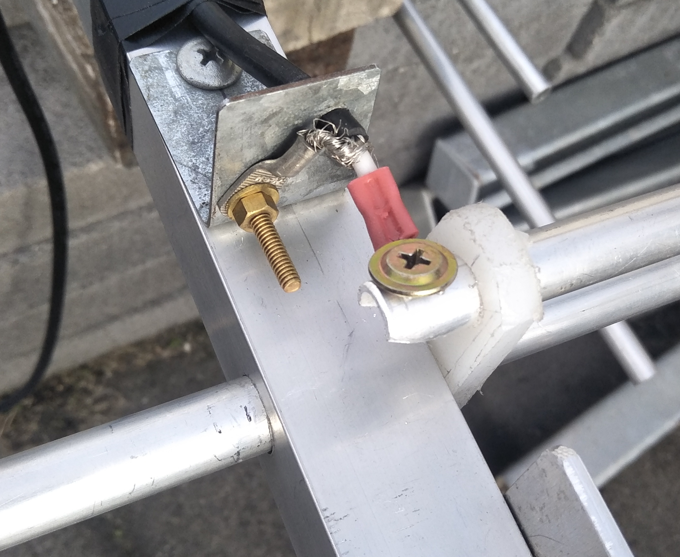
Feed point:
I
used a fly lead, a short 400mm section of RG58 with an inline SO239
connector at the other end.
The
other end was stripped about 15mm and brought through a bit of
galvanised plate bent at right angle which is secured to the boom
using self drilling screws.
Make sure the coax outer protrudes about
6mm through. A couple of lugs were fitted to the coax ends and the
braid secured to the metal plate and coax centre secured to the
matching rod.
Feed
point:
All
this is then thickly coated in epoxy resin (5 minute araldite or
similar) to seal the coax and connections from moisture. Cover all
this with tape or plastic to prevent sunlight UV degradation of resin
over time.
To
weatherproof the coax joining connector I used a 600mm length of
heatshrink over my feeder RG8 and RG58 with both open ends of the
heatshrink pointing down.
Tuning:
Is
done using your favourite method. Adjusting the element length moves
the frequency of lowest point of SWR, and the strap position adjusts
for
lowest SWR at that frequency.
These adjustments do interact slightly.
I tuned mine on a short pole at about 2m off the ground so that
adjustments were easy
to reach.
Just make sure that you are reasonably clear of large metal objects
i.e. cars and sheds, and pointed away from same.
Once
satisfied do a check in the final installation location. If happy
then rivet the driven element end sections in position and then tape
element joins and seal ends of elements (silastic) as a measure to
prevent water corrosion in joins.
I
tuned mine to lowest SWR at 50.290 so that it is usable from 50.000
to 50.500
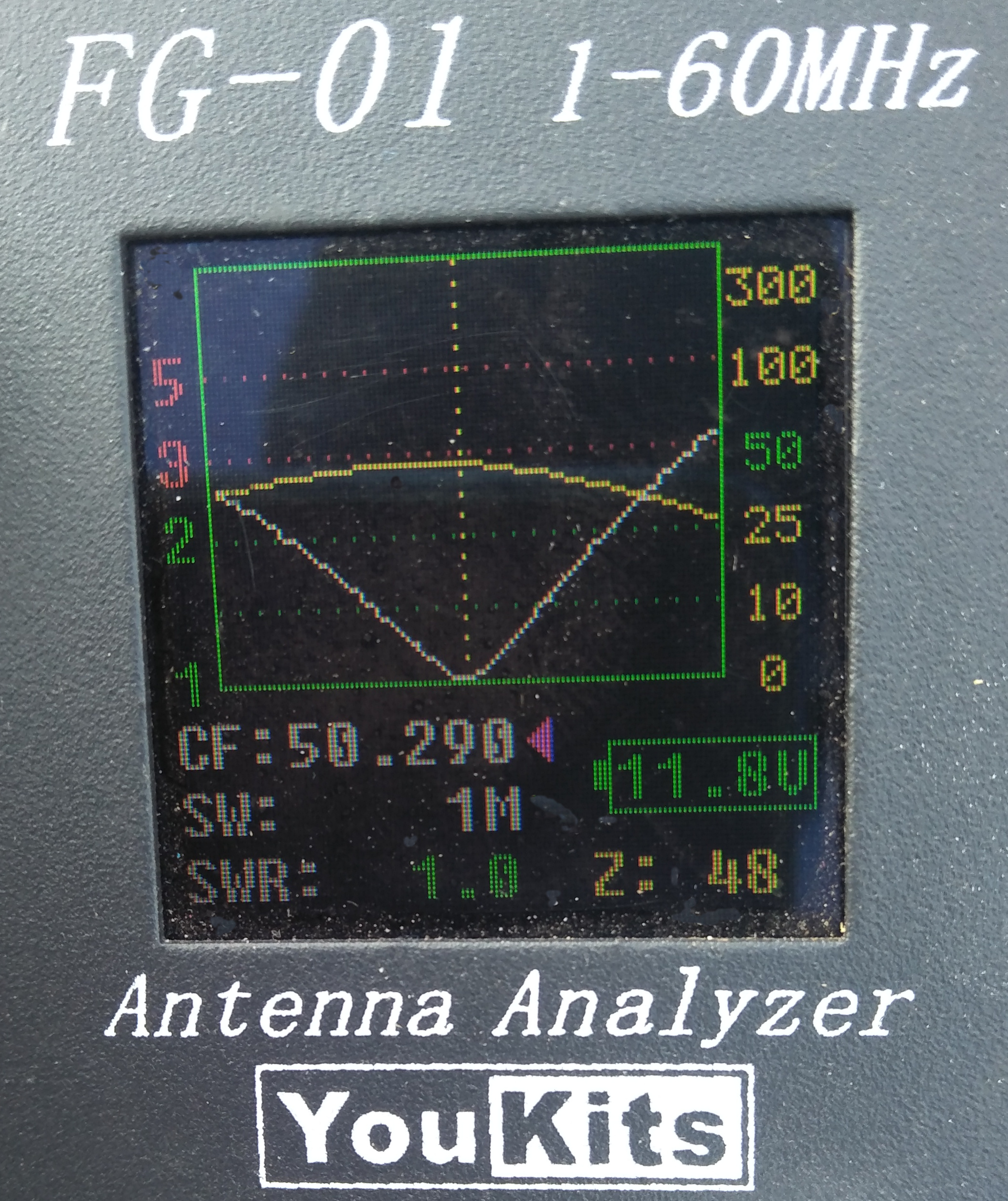
SWR
/ Impedance sweep is 1mhz wide
VK7DC
HOME
|